


Section 4 contains information on the PE-104 Vibrator Supply. Vibrator info. Testing using low voltage AC and Capacitor replacement.
INDEX
Click to Navigate
Version
ID
Ballast Info.
Vibrator
and Test Tools
PE-104 Testing
using low voltage AC
PE-104 Capacitor
replacement
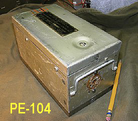
When the BC-654 set is powered by the dynamotor PE-103 utilizing a large vehicle battery the PE-104 vibrator supply is powered by the same battery. The PE-104 shown here will provide all the necessary receiver voltages as well as low voltages needed by the Transmitter. The PE-104 vibrator supply can be powered by 6 or 12 volts selectable by internal switch (red arrow) mounted on the power supply.
Receiver
power provided by the PE-104.
Filament
-1.5V
Plate 90V
Bias - On the receiver
it is approximately -6 from the PE-104 or approximately -
45 volts from the combined BA-43 battery returns of +90
and -45. This receiver bias voltage is not
critical and is used for bias on the volume/RF control circuit.
Transmitter
Power (low voltage) supplied by PE-104 or BA-43
Crystal
oscillator filaments -1.5 and carbon microphone bias.
Xtal
oscillator B +
Bias
-45V Final Power Amplifier Tubes Suppresser Grid modulation.
Identify which version of the PE-104

Click to enlarge RED arrows indicate early set components.
Shown above early schematic of sets up to serial #12000. Red arrows indicate components that were eliminated on later sets. The heavy black line is "Radio Ground" which is not connected to the chassis. Get used to the idea of a "floating" electrical ground that is not connected to the chassis.

Inspect the area near the rotary switch for three chokes indicating that you have a early version of the PE-104. Chokes missing ? - then you have a later model of the power supply.
Ballast Info

CLICK to enlarge
Later versions of the PE-104 had a Ballast Rectifier added to the -1.5 (minus 1.5) volt filament circuit to aid regulation. The heavy black line is "Radio Ground" which is not connected to the chassis. This Radio Ground is at a "Positive" potential for the lower voltages and at a Minus potential for the high voltage and is isolated from the chassis. All voltage measurements use the "Radio Ground" as reference.

PHILA-45-10
order describing the addition of the Ballast Rectifier 4A3.

High voltages are present in the PE-104 vibrator power supply. The high voltage circuits do not have bleeder resistors and capacitors need to be discharged prior to performing maintenance.

Ballast Rectifier
The low voltage filament Ballast Rectifier location is near the "Voltage Change Switch" 4S1. Your unit may not have the Ballast installed. All the ballast rectifiers in several power supplies that I have repaired were either shorted and completely shunted the voltage to "zero" or they were deteriorated to the point where the voltage dropped was excessive and the overall filament voltage was not adequate for the radio. The 1.5 volt filament supply will be discussed later on these pages and in Part 5 of this series.

Ballast Schematic. Note the polarity of the rectifier. The filament Bridge Rectifier circuit provides a -1.5 (minus one point five) voltage to pin 4 of the octal socket 4K1.

Click
to enlarge TM 11-310 schematic.
This
version of the schematic can be found in TM 11-310 in the rear section.
It is listed in the manual index as "Power Converter Unit PE-104."
Two schematic versions are contained in TM 11-310. Neither schematic
in TM 11-310 have the ballast depicted.
More
Ballast info in Part 5.

Download the applicable pages of TM 11-275.
Download the applicable page of TM 11-310.
 Ballast
Q. What was the Ballast used for?
A. Over voltage regulation of the 1.5 volt filament voltage.
Q.
Why is over voltage regulation of the 1.5 volt filament buss important?
A. Tube life. High voltage is bad.
Q.
How efficient was the Ballast?
A.
Not very efficient but used primarily to prevent over voltage.
Q.
How could a over voltage of the 1.5 volt buss occur?
A. Varying input voltage could cause a over voltage. For example
when using the set in a vehicle the input voltage could be as much as
7 volt or 14 volts depending on the setting of the vehicle voltage regulator.
In addition according to the TM different vibrators could produced different
voltages because of the "switching" efficiency. This did not
result in a problem on the High Voltage circuits as they would continue
to function with a voltage variance of several volts but the 1.5 volt
filament buss is fairly critical. Please reference TM 11-275 paragraph
35.
Q. Is the Ballast constructed of Selenium Material? It looks like a Selenium Rectifier.
A.
Actually according to the parts list it is made of MG-CU Sulphide. (Magnesium
Copper Sulphide)
Q.
I've read that selenium rectifiers age and the voltage drops. Do these
MG-CU Sulphide rectifiers have the same characteristic?
A.
Probably.
Q.
Can I test a Ballast rectifier with my VOM?
A.
Maybe. You cant use the Diode test on a Digital Multimeter but testing
each side using the Mega Ohms range may work. Its best to get a real analog
meter and use the highest resistance range.
Q. Why was the Ballast not installed in some sets?
A. Different Signal Corps Order Numbers has the Ballast.
There were thousands of the PE-104s manufactured in many different locations
under a different "Order Numbers". In general the Ballast was
installed in later models of the power supply.
Q.
I can't find the Ballast listed in the TM 11-275 parts list.
A. Neither can I. It might be listed in later TM's.You can look up Bridge
Rectifier 4A1 it has similar construction.
Q.
How about using a couple of 1 Amp diodes in series as as a ballast?
A. Experimenting with several different diodes and using 2 power
supply diodes resulted in a voltage of 1.5 to 1.8 volts. Different diodes
will have slight different voltage drops. Four (4) Schottly diodes (The
string of four dissipates heat better) resulted in a 1.6 voltage drop.
Remember that the voltage drop may increase as current increases depending
on the diode. On several of my supplies I just ignored the ballast and
installed a better voltage regulator or varied the transformer circuit
bridge diodes for the 1.5 volt buss on the output winding of the transformer.
Since all the ballast's that were installed in my power supplies were
shorted I just eliminated the wiring. Consider heat sinks for any diodes
that are used to replace the Ballast.
Q.
How about using a zenier?
A. There are no standard zenier diodes in the 1.5 volt range.
Q.
How about using other voltage sensor circuits.
A. Most of the voltage sensor ICs will not operate in the 1.5 volt range.
Q. I am getting paranoid about my ballast circuit as it was originally installed. I want every thing to be original.
A. If your ballast is OK then go with it. I personally don't like the ballast circuit. Read all the information on these pages and in part 5. My goal is to have a working power supply with a reliable 1.5 volt filament voltage. I like for my sets to work and I like to enhance tube life.
Q.
Why not just install a voltage regulator IC.
A. Good idea but you will need a higher voltage input such as 6 or 12
volts and use a "Negative" voltage regulator such as a LM 337.
But first you may not need an additional regulation circuit. Get your
power supply running and then check your 1.5 volt voltage "under
load" IAW the TM 11-275 paragraph 35 b and sketch (d).
More info on the 1.5 volt buss is presented later in Part 5.
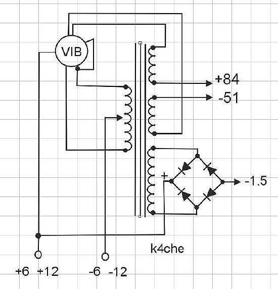
 Note
all voltages are measured under load. Without a load the voltages will be
higher.
Note
all voltages are measured under load. Without a load the voltages will be
higher. The main schematic of the PE-104 can be a little daunting to study but to get the general idea of the power supply a block diagram is presented. Please note that the vibrator has a extra set of contacts that perform a rectification cycle on the HV and Bias windings. Its PFM The 1.5 volt supply has its own bridge rectifier and provides the filament voltage at a negative potential. The Ballast circuit is not shown.
The next section will discuss the vibrator followed by a
section on testing the supply using low voltage AC in place of the vibrator.
This "AC" procedure may come in handy and allow trouble shooting
of basic power supply components. Vibrator replacement with a solid state
unit and additional filament regulation will be discussed in Part 5 of this
series. Test
Tools

An extension cable fabricated from standard 8 pin octal plug and socket.

When wiring your plug add extra bare wires to be used for meter probe tabs.

Test board for the power supply. 6 or 12 volt input on the right. Pad connections at the top represent pins 1 through 8 on the octal connector. Use a 3.5 ohm resistor to test the -1.5 volt filament supply under load. Use a 100K resistor to test the bias under load. The test board is a simple project and will save a lot of time.

Resistor Test
load for the -1.5 volt filament buss. Adjusted to 3.5 (three point five)
ohms.
There are plenty of 3.5 ohm resistors on ePay but I prefer to use an adjustable
pot and monitor current on my Simpson 260. A large power pot is shown
above but the 1.5V circuit only consumes approximately a couple of watts.
You should measure approximately 400 ma with all filaments active.
Buffer
Capacitor

RED
arrow points to the buffer capacitor.
As a general rule when working on older vibrator supplies you should replace the "Buffer Capacitor". Red arrow points to 4C1 a .2(point two) uF cap. It is fairly difficult to remove 4C1 from the chassis as it is held in by a robust bracket. Additional Info: Yellow arrow points to the original -1.5 volt bridge rectifier. The Green arrow points to the original Ballast Rectifier 4A3.

I used two .1 uF caps in parallel on this power supply to replace the buffer capacitor 4C1. Look carefully you will see that the bridge rectifier for the -1.5 volt buss has been replaced. In addition the Ballast Rectifier is MIA. A 1.5 volt negative regulator circuit has been installed in the upper right of the chassis. More info below.

The vibrator housing can be carefully pried opened. Don't get in a hurry.

Synchronous
Vibrator - note the dual pair of contacts and the Normally Closed pair
on the bottom.
The NC (normally closed) contacts have to be closed and make good contact
in order to start the "buzzer" action of the vibrator. Note
the position of the long center contact arm that will swing toward the
center of the magnet when DC is applied to the coil. This will help in
identifying the NC contacts.

Deoxit can be applied to a thin piece of card board and utilized to clean the contacts. More information on vibrator trouble shooting and testing can be found in my Electric Radio article published in August of 2014. Link below.
Links provided below for additional Vibrator Information

CLICK here for a Vibrator Article published in "Electric Radio"

Do your self a favor and remove the vibrator clamp from the chassis. It is a PITA. Adjusting the clamp fingers on the side is futile and it is hard to adjust the clamp when it is installed on the chassis.

Arrows on top of the vibrator aid in lining up the large pins for insertion. The white lanyard is attached under the vibrator to aid in extraction. Note the two "New" capacitors on the left, More info on capacitor replacement below.

Stuck vibrator?
When attempting to pull out a stuck vibrator you can try pushing from under the socket on the large and small pins with a probe. Be careful and take your time.

Pins 6 and 1 are larger than the other pins. View shown above is looking down at the top of the socket mounted in the chassis. .

Info: Pin numbers were missing on the early schematic figure 20. I hope I didn't screw this up.

Socket Pins. The large pins are #6 and #1. Pin #2 is easy to identify as it connects to the buffer capacitor 4C1. The buffer wire was painted Red when I was working on the unit.
Vibrators
Q.
Can I substitute a standard non Synchronous vibrator by jury rigging the
vibrator plug ?
A.
Yes but diodes will have to be added on the chassis below the vibrator
socket to provide rectification for the HV and Bias circuits. One diode
for the HV and one diode for Bias. The filament supply (1.5 volts) on
the PE-104 has its own bridge rectifier.
Q. Can I use a 6 volt substitute vibrator on the PE-104 when I am using a 12 volt battery to power the radio set?
A. Yes the PE-104 has a voltage switch which selects appropriate taps on the transformer.
Q. What is the operating frequency of the vibrator circuit?
A. 115 cycles per second.
Q. I hate mechanical vibrator power supplies.
A. Me too.
Q. Is there a electrical substitute for the vibrator.
A. I thought you would never ask. YES. See Part 5 of this series.
Low
Voltage AC Testing. Vibrator not needed.

CLICK
to enlarge
Low voltage AC such
as output from a 6.3 volt filament transformer may be used to provide
a input voltage to transformer 4T1 for testing of the PE-104 circuits.
REMOVE VIBRATOR. Temporary diodes will be soldered on the vibrator socket
pins for the HV and Bias windings half wave rectifiers.
Disconnect
radio
Remove
Vibrator
Install
Diodes
Select
12 V on the PE-104 for initial testing.
Apply
6.3 volts
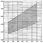
When bench testing with an external AC voltage such as
6 volts you can expect the PE-104 power supply output voltages to only
approximate the published values. Do not connect the PE-104 to your radio
unless you are certain the voltages are within specifications and tested
under load. A variac on the filament or similar transformer input
can come in handy.

Suggested Diodes : 1N5408 General Purpose Rectifier Diode 3A 1000V. Any general purpose power supply diode will suffice.

Temporary diode soldered in place on pins 2 and 6 to test the high voltage winding and output. Low voltage AC will be wired to pins 1 and 5 for this bench test in order to check out major components.
 A
solid state vibrator board can be substituted for the vibrator. More info
in Part 5 of this series.
A
solid state vibrator board can be substituted for the vibrator. More info
in Part 5 of this series. 
Most
of the large value capacitors are easily replaced if necessary.

Hum on the receiver? Check 4C15. It was very leaky on several of my power supplies. The newer capacitor (blue) is slightly smaller. 4C15 is a 4500 uF and is the main filter for the 1.5 volt filament buss. Note the arrows on the vibrator to aid in alignment during insertion.
High voltages are present in the PE-104 vibrator power supply. The high voltage circuits do not have bleeder resistors and each circuit needs to be discharged prior to performing maintenance.

Photo:www.electricaltechnology.org
sketch
A preliminary check can be made on the capacitors using a ohm meter. A more detailed evaluation of a capacitor can be made using a capacitor analyzer.
First discharge the capacitor by applying a short across the terminals. Disconnect one wire. Using an ohm meter the cap will initially show a low resistance and then gradually increases toward the infinity. This indication means that Capacitor passes the preliminary test. An Intermediate reading of thousands of ohms indicates a leaky cap. Try this resistance test on a good capacitor for practice.

As you explore the wiring using the "Connection Diagrams" - label the caps in case you have to come back to a section to trouble shoot.

CLICK
to enlarge
Multiple capacitors may not be arranged in numerical
order. The 4C10 through 4C13 bank are mounted out of order. The order
goes 11-10-12-14-13 with 13 being at the bottom next to the chassis.
Consult the "Connection Diagrams".

Label as you go through the circuits it will help with trouble shooting.

Possible
suspect capacitors to be replaced.
In several power supplies the 4C15 and 4C2 were leaky and replaced.
Part 5 will discuss the solid state vibrator replacement, Filament voltage and Bias voltage adjustment and more Ballast information.